WELDTRONIC ENGINEERS
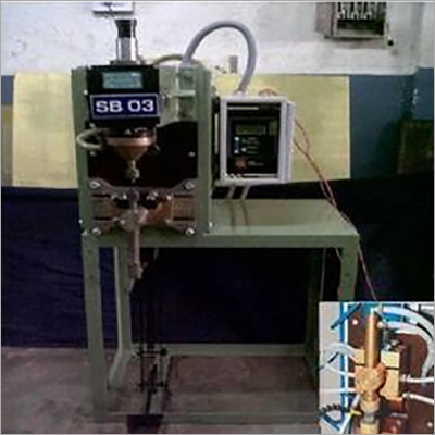
PROJECTION CUM SPOT WELDING MACHINE
Product Details:
X
Product Description
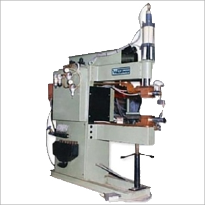
MACHINE DESCRIPTION
KVA RATING:
The transformer will be air cooled step down 100 kVA 2 Phase 440 VAC 50 % duty cycle with 4 taps for variable voltage.
MACHINE BODY
Reinforced fabricated steel structure with louvered covers for well ventilation. Simply supported type, heavy section fabricated upper and lower arms fitted directly on the machine. Upper arms carries friction or anti-friction ram along with the weld electrode assembly. Lower arm carries the lower weld electrode assembly with ample section bus bar. The upper and lower arm are constructed such a way that even under heavy pneumatic pressure, minimum deflection occurs. Main transformer is housed in the basic body.
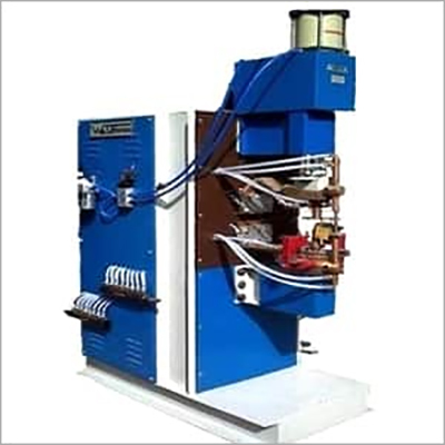
WELDING TRANSFORMER
A heavy duty transformer made as per IS - 4804 Part 1 is used as the main power source. Special sandwich construction of coils helps to increase the coupling between the windings and offers maximum efficiency. Primary and secondary conductors are selected to suit the heavy demand current. Copper cooling tubes are brazed throughout the periphery of the secondary segments. Transformer core is made out of cold rolled grain oriented lamination sheets to reduce the core losses. Class F insulation materials used in the transformer help to withstand a temperature of up to 155oC. The coil assembly is varnished in F 50 varnish and vacuum impregnated. A special thermo switch fitted on the secondary segment helps to cut out the control circuit when the temperature of the winding rises above the safety level, thereby protecting the transformer from overloading.
RAM
Anti friction ram is used for electrode and cylinder attachment with brass bush in which the induction hardened tail or pilot rod will be sliding to properly guide upper electrodes.
PNEUMATIC SYSTEM
The basic pneumatic system consists of a pneumatic double acting cylinder, solenoid valve of 4 way 5 port, filter, lubricator, regulator, gauge and foot operating initiating switch for solenoid coil. The precision honed and lapped pneumatic cylinder, both sides cushioned, is directly connected to the ram with the help of coupling. Electrode force is varied by means of the air regulator knob.
All the current carrying components are internally water cooled and hence no external water spraying is required as in the conventional machines. The upper and lower bus bars are provided with built in water jackets.
ELECTRONIC CONTROL SYSTEM
The Micro Processor Control is housed in a desk type control cabinet, which is normally suited for separate floor mounting. All the control knobs are housed on the desk behind a transparent acrylic guard door to prevent misuse by unauthorized persons. The control circuits used in the system are based on the latest technology of IC’s, transistors and thyristors. For easy operation and maintenance, all cards are modular type and wherever necessary, sturdy plugs and sockets are used for easy service. The control and foot switch circuit is connected to a low, safe and isolated control voltage.
The foot switch will initiate the solenoid valve of the pneumatic cylinder and simultaneously the squeeze timer will energize the weld control, after the time set (1 - 100 cycles). A fully synchronous digital timer of "0 - 100 cycles ON " and "0 - 100 cycles OFF " will feed exact "ON - Of" pulses to the heat control card. The heat control card generates pulses, which triggers the thyristor switch. The current of the welding transformer can be adjusted from 5% to 100% by means of the phase shift firing of the thyristor switch.
UPPER AND LOWER WELD ELECTRODE ASSEMBLY
Consists of copper alloy weld electrodes of suitable section of hardness 68 Rockwel B scale, weld electrode holders, high percentage of copper content phosphor bronze bushing and water cooled holders of ample section copper alloy casting.
POWER ELECTRONIC CONTROL SYSTEM
The thyristors, matching the KVA of the transformer connected, in inverse parallel constitute the thyristor switch. The thyristor switch is mounted on an ample water cooled heat sink section to facilitate smooth and efficient current switching to the welding transformer for continuous welding operation, without appreciable change in the heat sink temperature. Protection devices like thyrectors for high voltage transcients and thermoswitch for heat sink temperature control is incorporated. Hold timer is provided to stop the welding current, before separation of welding wheels. The range of timer is 1 - 100 cycles.
WATER COOLING SYSTEM
All the current carrying components are internally water cooled and hence no external water spraying is required as in the conventional machines. The upper and lower bus bars are provided with built in water jackets. Water Pump will also be provided with the machine.
Spot Welding Machine Features :
- The machine body will be made out of Reinforced Fabricated Steel Structure with good ventilation
- The upper & lower arms will be robust type fabricated from heavy section.
- The main Transformer will be housed in the Basic Body
- Heavy duty Transformer will be Made as Per IS - 4804 Part I as the Main Power Source.
- Copper pipes will be used as secondary segments in which water will be passed for water cooling.
- The insulation of the Transformer will be class F to withstand Temperature upto 1550C
- The coil assembly will be varnished in F 50 varnish & vacuum impregnated.
- Special Thermo switch will cut out the Control circuit when the Temperature rises above the safety level protecting the Transformer from Overloading
- Upper & lower weld Electrode assembly will consists of Copper alloys suitable section of hardness 68 (Rockwell B scale)
- Weld Electrode shafts, high percentage of Copper content phosphor Bronze bushing & water cooled holder will be of ample section copper alloy casting.
- The pneumatic systems will consists of a pneumatic double acting cylinder, solenoid valves of 4 way 5 port, Filter, Lubricator, regulator, gauge & Foot operating initiating switch for solenoid coil
- Air regulator knob will be provided for varying Electrode Force
- All the current carrying components will be internally water cooled. The upper & lower bus bars should be provided with built in water Jackets
- Electronics Control System will be housed in a desk type control cabinet. All the control
- knobs should be housed So as to prevent the Misuse by unauthorized persons. The control circuit used in the systems should be based on the latest technology
- A fully synchronous digital timer of 0-9 cycles ON-OFF will feed exact pulse to the heat control card
The Current of the Transformer will be adjustable from 5% to 100 % by thyristor switch
Machine Specification :
| KVA Rating at 50% Duty Cycle | 100 |
| Air Cylinder Dia. (In mm) | 150 |
| Cylinder Stroke (mm): | 100 |
| Electrode Force (in kgf): | 440 |
| Work Stroke in (mm) : | 50 |
| FIL / LUB / REG / Gauge BSP : | 1/2" |
| Short Circuit Current : (In KA Throat 750 mm): | 15 |
| Rate of Water Flow : | 13 l/min |
| Free Air consumption for 100 Operation with 25 mm. Maximum Working Stroke Ltr. : | 200 |
| Supply Cable Size copper mm. sq. : | 40 |
| Main Supply Switch fuse rating in Amps : | 100 |
| H.R.C Fuse rating in Amps : | 90 |
| Primary Amps : | 75 TO 100 |
| Weld Cycle Time : | 10Hz |
| Control | Micro Processor Based Slope Control |
| Dimensions in mm. (LxBxH) | 1225 x 815 x 2042 |
| Weight | 670 k.g.s. |
Other Products in 'Spot Welding Machines' category
WELDTRONIC ENGINEERS
All Rights Reserved.(Terms of Use)
Developed and Managed by Infocom Network Private Limited.
Developed and Managed by Infocom Network Private Limited.


