WELDTRONIC ENGINEERS
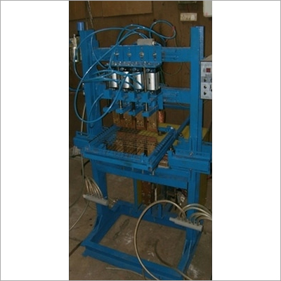
Automatic Spot Welding Machine
Product Details:
X
Product Description
SEQUENCE OF OPERATION
The Automatic Spot Welding Machine sequence begins with a press of a foot switch which starts the whole automatic welding process, but before that the job needs to be made sure it is fit in the removable electro-magnetic fixture. After the job is tightly fit in the fixture, the job is pushed along with the linear bearing slide till it touches the proximity switch or job fixture sensor. Soon as the job is sensed top right and bottom left cylinder operates after a delay that is pre set in the PLC.
During this operation when the top right and bottom right cylinder meet at the business / slash welding region, current passes through the electrodes after a certain delay and the cylinders move back to their retracted position. Sensor is detected at the top right side of the machine due to the retraction and the top cylinder initiates the top left and bottom left cylinder to operate again to spot weld at the welding zone an return back to its original position. Here again another sensor is detected which initiates the gripper actuator and causes it to grip the fixture bottom, as the gripper pressure increases to 40 p.s.i the load cell in built in the gripper initiates the slider cylinder which slides up to the distance programmed by the user.
After the slider has reached another detectable point or sensor the potential free contact of the sensors closes with the first sequence, which means sequence a will continue till the no. of stages set in the plc is reached for Eg. if 4 rows are set then 8 spot welds will take place, 3 indexes will be completed, so on and so forth
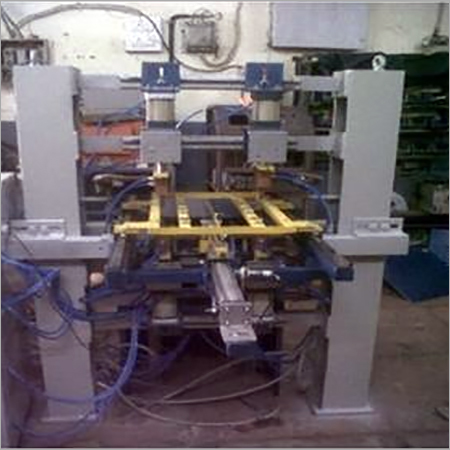
DESCRIPTION OF MACHINE :
- BODY - The bod is made out of robust ms structure. The base is manufactured / fabricated by with channels and the vertical columns with I beams. The Tee slot bar is welded on a 50 x 50 angular box. Two nos. of boxes are welded horizontally on frame upon which two horizontal tee slot bars are welded to carry the pneumatic cylinder attachments on upper and bottom side on the front side of the machine body
- PNEUMATIC CYLINDER ARRANGEMENT - There are 4 pneumatic cylinders totally, two on top and two bottom. The cylinders used on top are 65 dia x 50 mm. stroke and bottom cylinders are 65 dia.x 25 mm. stroke. The pneumatic cylinders are mounted on slotted angles for X axis movements upto 500 mm. and Y axis movements upto 50 mm.
- LOWER ELECTRODE HOLDER AND BUSBAR ASSEMBLY - The lower electrode holders are connected with the lower busbar assembly and the busbar connected to transformer power source. All busses are water cooled with aluminum heat sinks.
- UPPER ELECTRODE ASSEMBLY- . Phase L1 of bottom electrode is connected to R phase of trx and Phase L2 of upper electrode is connected to Y phase of transformer. The connections to the trx and electrode holders are made with flexible copper links. The upper electrode holder and electrodes are water cooled and aluminium water cooled heat sinks are provided at all flexible and rigid link contacts.
- FIXTURE - The fixture is made of cold rolled closed annealed sheet metal and fibre. The fibre is an insulation in between the sheet metal and trolley. The job is loaded on the fixture locating pin and the pins are electromagnetically charged at the time of welding only so that the job does not shift from its designated position.
- TROLLEY SLIDE - The trolley is fabricated of angular boxes and welded on the column of the spot welding machine. The trolley system carries a pneumatic slide of 50 dia and 300 mm stroke, the pneumatic slide carries the pneumatic gripper
- GRIPPER - The gripper used for the gripping and releasing of job is a pneumatic actuator of 25 dia bore and 25 mm. stroke The fingers of the gripper are spring opposed to grip jobs firmly and that the job should not slip at the time of sliding.
Other Products in 'Multi Spot & Wire Mesh Welding Machine' category
WELDTRONIC ENGINEERS
All Rights Reserved.(Terms of Use)
Developed and Managed by Infocom Network Private Limited.
Developed and Managed by Infocom Network Private Limited.


