WELDTRONIC ENGINEERS
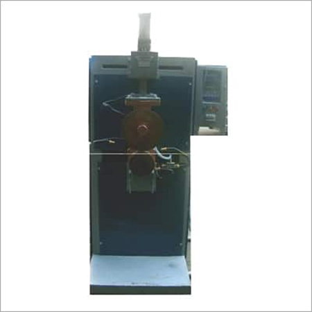
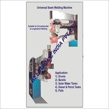
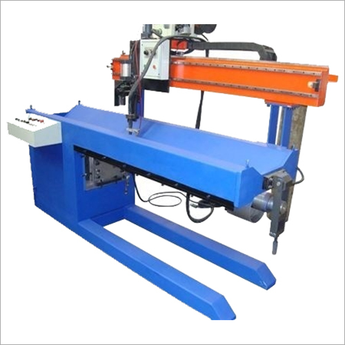
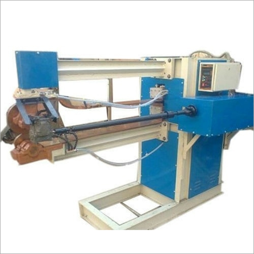
Circumferential Seam Welding Machines
Product Details:
X
Product Description
Features :
- 1) No skilled person required
- 2) Faster welding compared to Conventional welding
- 3) Aesthetically better looking Welds and non conspicuous
- 4) Strong leak proof welding is achievable without Repeated welding trials
- 5) Circumferential welding can be done on a single stroke/go
- 6) No filler rod material is required for welding
- 7) Long life electrode wheels ensure maintenance is very low compared to normal welding operations and procedures.
- 8) Micro Processor based seam welding control.
- 9) 20 storable programs which means 10 different jobs can be welded and welding parameters saved with no need to re enter welding parameters each time, before beginning welding process.
- 10) Ac Variable Frequency drive is incorporated to vary speeds of wheel based on electrode consumption
Application : Diesel Tank , Radiators, Solar Tank Dish, Kitchen Sink
Clients : Mahindra N Mahindra, Ashok Leyland, Kamal Solar, Suntek Solar, Sunzone Solar
Machine Description & Manufacturer’s Scope of Supply
KVA RATING
100 kVA, 100 % duty cycle, 440 VAC 50 Hz Frequency power source, air convection cooled, secondary pipe water cooled step down transformer will be standing type More details in Transformer section.
MACHINE BODY
Reinforced fabricated steel structure with well ventilated covers Simply supported type, heavy section fabricated upper and lower arms fitted directly on the front side of the machine Upper arms carries friction or anti-friction ram along with the upper weld wheel assembly Lower arm carries the lower weld wheel assembly with ample section bus bar. The upper and lower arm are constructed such a way that even under heavy pneumatic pressure, minimum deflection occurs. Main transformer is housed in the basic body.
WELDING TRANSFORMER
A heavy duty transformer made as per IS - 4804 Part 1 is used as the main power source Special sandwich construction of coils helps to increase the coupling between the windings and offers maximum efficiency Primary and secondary conductors are selected to suit the heavy demand current Copper cooling tubes are brazed throughout the periphery of the secondary segments. Transformer core is made out of cold rolled grain oriented lamination sheets to reduce the core losses Class F insulation materials used in the transformer help to withstand a temperature of up to 155º C The coil assembly is varnished in F 50 varnish and vacuum impregnated. A special thermo switch fitted on the secondary segment helps to cut out the control circuit when the temperature of the winding rises above the safe level, thereby protecting the transformer from overloading.
UPPER AND LOWER WELD
WHEEL ASSEMBLY
Consists of copper alloy weld wheels of suitable section of hardness 68 Rockwell B scale, weld wheel shafts, high percentage of copper content phosphor bronze bushing and water cooled holders of ample section copper alloy casting.
RAM
The ram assembly will consists of hardened and ground guide rail with guide block. The guide-rail mounted on body frame whereas the guide block to be will reciprocated along the pneumatic cylinder direction. This type of ram assembly assures prompt cylinder response time for forward and reverse motion, also the ram system is isolated from weld wheel assembly to avoid the rail ball bearings to get burnt.
PNEUMATIC SYSTEM
The basic pneumatic system consists of a pneumatic double acting cylinder, solenoid valve of4 way 5 port, filter, lubricator, regulator, gauge and foot operating initiating switch for solenoid coil. The precision honed and lapped pneumatic cylinder, both sides cushioned, is directly connected to the ram with the help of coupling Electrode force is varied by means of the air regulator knob.
ELECTRODE DRIVE SYSTEM
An AC motor is mounted on the upper arm Reduction gear unit with variable drive is always directly coupled to the weld wheel shaft Hence no wheel slippage will take place as in the case of direct knurl drive Knurling device will be directly mounted on the upper or lower weld wheel. The dressing pressure can be adjusted by means of a spring provided in the knurl wheel assembly.
WATER COOLING SYSTEM
All the current carrying components are internally water cooled and hence no external water spraying is required as in the conventional machines. The upper and lower bus bars are provided with built in water jackets.
ELECTRONIC CONTROL SYSTEM
The Micro-Processor Control is housed in a desk type control cabinet, which is normally suited for separate floor mounting. All the control knobs are housed on the desk behind a transparent acrylic guard door to prevent misuse by unauthorized persons. The control circuits used in the system are based on the latest technology of IC’s, transistors and thyristors. For easy operation and maintenance, all cards are modular type and wherever necessary, sturdy plugs and sockets are used for easy service. The control and foot switch circuit is connected to a low, safe and isolated control voltage.
OPERATION AND WORKING
The foot switch will initiate the solenoid valve of the pneumatic cylinder and simultaneously the squeeze timer will energize the weld control, after the time set ( 1 - 250 cycles).
A fully synchronous digital timer of “ 0 - 9 cycles ON ” and “ 0 - 9 cycles OFF ” will feed exact“ ON - Off ” pulses to the heat control card. The heat control card generates pulses, which triggers the thyristor switch. The current of the welding transformer can be adjusted from 5%to 100% by means of the phase shift firing of the thyristor switch.
The thyristors, matching the KVA of the transformer connected, in inverse parallel constitute the thyristor switch. The thyristor switch is mounted on an ample water cooled heat sink section to facilitate smooth and efficient current switching to the welding transformer for continuous welding operation, without appreciable change in the heat sink temperature Protection devices like thyrectors for high voltage transients and thermo switch for heat sink temperature control is incorporated Hold timer is provided to stop the welding current, before separation of welding wheels The range of timer is 1 - 100 cycles.
Customer’ Scope :
- 100 Amp Switch Fuse Unit 3 Pole- 1 No.
- 3 HP Pneumatic Compressor- 1 No.
- 500 ltrBasin 1.5T Cooling Tower - 1 No.
SEAM WELDING MACHINE FEATURES :
- The machine body will be made out of Reinforced Fabricated Steel Structure with good ventilation
- The upper & lower arms will be robust type fabricated from heavy section.
- The main Transformer will be housed in the Basic Body
- Heavy duty Transformer will be Made as Per IS - 4804 Part I as the Main Power Source.
- Copper pipes will be used as secondary segments in which water will be passed for water cooling.
- The insulation of the Transformer will be class F to withstand Temperature upto 155oC
- The coil assembly will be varnished in F 50 varnish & vaccum impregnated.
- Special Thermo switch to cutout the Control circuit when the Temperature rises above the safety level protecting the Transformer from Overloading
- Upper & lower weld Wheel assembly should consists of Copper alloys suitable section of hardness 68 Rockwell B scale
- Weld Wheel shafts, high percentage of Copper content phosphor Bronze bushing & Water cooled holder should be of ample section copper alloy casting.
- The pneumatic systems will consist of a pneumatic double acting cylinder, solenoid valves of 4 way 5 port, Filter, Lubricator, regulator, gauge & Foot operating initiating switch for solenoid coil
- Air regulator knob will be provided for varying Electrode Force
- All the current carrying components will be internally water cooled The upper & lower bus bars should be provided with built in water Jackets
- Electrode drive system will consist of a Motor with thyristorised Speed Control Unit
- Electronics Control System will be housed in a desk type control cabinet All the control knobs should be housed. So as to prevent the Misuse by unauthorized persons. The control circuit used in the systems should be based on the latest technology
- A fully synchronous digital timer of 0-9 cycles ON-OFF to feed exact pulse to the heat control card
- The Current of the Transformer will be adjustable from 5% to 100 % by thyristor switch
Machine Specifications :
| Throat Depth | 300 mm. |
| KW Rating at 100% Duty Cycle | 100 |
| Air Cylinder Dia in mm | 100 |
| Stroke mm | 50 mm. |
| Electrode Force in kgf | 990 |
| Ram Stroke in mm./ Work stroke | 35 |
| FIL / LUB / REG / Gauge BSP | 1/2 |
| Short Circuit Current | 20kA |
| In KA Throat300 mm. | 29 |
| Rate of Water Flow (lpm) | 25 |
| Free Air consumption for 100 Operation with 25 mm Maximum Working Stroke Ltr. | 200 |
| Supply Cable Size copper (mm sq.) | 35 |
| Main Supply Switch fuse rating in Amps | 150 |
| H.R.C Fuse rating in Amps | 145 |
Job Specifications :
- Material : S.S304 / 316 / M.S.
- Thickness : 0.6 to 1.5 mm.
- Bore : 300 - 800 mm.
Other Products in 'Seam Welding Machine' category
WELDTRONIC ENGINEERS
All Rights Reserved.(Terms of Use)
Developed and Managed by Infocom Network Private Limited.
Developed and Managed by Infocom Network Private Limited.


